Business
QFD, Training, Process
Improvement, Process Mapping,
PDCA, Simulation,
Process Analysis, Process
Metrics,
Management & Planning Toolkit
Business
QFD
 QFD,
described in some detail in the Philosophy
page of this section, provides an excellent tool for thinking
through the business processes and what they should deliver. QFD,
described in some detail in the Philosophy
page of this section, provides an excellent tool for thinking
through the business processes and what they should deliver.
Defining the Processes of the
company is not a precise science - there is no one perfect way
to subdivide the company - each different way will have its merits
and its disadvantages. The key thing is to identify a Process
Model (the list of processes for your business, and what they
comprise) which you believe will provide a clear (unconfused)
basis for managing the business, and which will provide insights
for improving the business.
The best way we have found of
doing this is to list the various activities of the business
on to sticky-notes, and split the management team up into syndicate
groups to develop proposed Process Models by grouping the activities
into a limited number of top level processes. On completion of
the syndicate exercise the strengths and weaknesses of the various
models are discussed, and a preferred model is selected - this
is further refined by drawing ideas from the rejected models
to address the chosen model's weaknesses.
The QFD provides a basis for
examining the potential of each process to contribute to the
achievement of the business objectives (positively or detrimentally),
and this analysis creates a framework for both analysing and
redesigning the process.
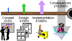 QFD
drives the Management to consider the correct organisation of
its processes in concept, and then to translate this understanding
into an appropriate design. Without this the cost of misalignment
or inefficiency in the process can prove very expensive, either
in terms of correcting it physically or in terms of the consequences
in overhead costs or loss of business. The diagram (right) illustrates
this: issues that would take minutes to address in the concept
stage, take hours if they have to be addressed in design (in
terms of changing procedures and plans etc.), take weeks if they
make it through to implementation (in terms of modifying or re-ordering
plant etc.), and can cost many times that if left as a general
inefficiency or weakness in the business. QFD
drives the Management to consider the correct organisation of
its processes in concept, and then to translate this understanding
into an appropriate design. Without this the cost of misalignment
or inefficiency in the process can prove very expensive, either
in terms of correcting it physically or in terms of the consequences
in overhead costs or loss of business. The diagram (right) illustrates
this: issues that would take minutes to address in the concept
stage, take hours if they have to be addressed in design (in
terms of changing procedures and plans etc.), take weeks if they
make it through to implementation (in terms of modifying or re-ordering
plant etc.), and can cost many times that if left as a general
inefficiency or weakness in the business.
[Return
to Top of Page]
Training
 The
concept of PROCESS is still not fully embedded in many companies.
A lot of companies still focus on departments and achievements,
rather than processes and performance. In part this is due to
their people not feeling fully confident in talking about business
processes - many have heard about Business Process Re-engineering
(BPR), and figure it is something you have 'done to you' unless
your lucky enough to avoid it until it fades away. The
concept of PROCESS is still not fully embedded in many companies.
A lot of companies still focus on departments and achievements,
rather than processes and performance. In part this is due to
their people not feeling fully confident in talking about business
processes - many have heard about Business Process Re-engineering
(BPR), and figure it is something you have 'done to you' unless
your lucky enough to avoid it until it fades away.
PROCESS as something you have
'done to you' will fade away, but PROCESS that you work through
for yourselves will not - it is far to powerful and effective
a concept for this to happen, and it will survive because the
companies that use it will survive.
PROCESS is a simple concept,
but to use it confidently and efficiently will require you training
your managers in the thinking and tools that lie behind it. Much
of this can be done in-house on-the-job by managers who have
gained these skills previously, and are using them with their
teams. To augment this you might consider specific training in
Process Mapping or Process Analysis.
[Return
to Top of Page]
Process
Improvement
 There
is a model of learning which demonstrates how we pass through
4 stages in assimilating a new skill. The stages are: Unconsciously
Incompetent - we don't know that we don't know; Consciously Incompetent
- we discover our weakness in a particular area; Consciously
Competent - we get training or develop the necessary skills;
Unconsciously Competent - we become so adept that it happens
naturally almost without us realising that we are doing it. To
understand this better you might think it through for something
specific - eg driving a car. There
is a model of learning which demonstrates how we pass through
4 stages in assimilating a new skill. The stages are: Unconsciously
Incompetent - we don't know that we don't know; Consciously Incompetent
- we discover our weakness in a particular area; Consciously
Competent - we get training or develop the necessary skills;
Unconsciously Competent - we become so adept that it happens
naturally almost without us realising that we are doing it. To
understand this better you might think it through for something
specific - eg driving a car.
The model of Process Improvement
(shown above left) is very simple to this, and describes a step-by-step
approach for developing learning within a business process:
Step 1: (Current Physical) The
process exists and produces a result, but there may be very little
overall understanding of what exactly happens when, how and by
whom, or even how well. All the understanding of the process
is hard-wired into people's jobs, machine programs, plant layout
etc.
Step 2: (Current Logical) The
process is mapped out so everybody can see exactly how it works
currently. The flow of activities, and how they are resourced
and controlled is understood. And the performance (time taken,
number produced, yield rate etc.) and the variability in that
performance is documented.
Step 3: (Future Logical) The
logical map developed above is considered for weaknesses and
inefficiencies. These are addressed by changing work flows and
activities, or by making other changes to resources or control
mechanisms. A new map is then developed to show how the process
needs to change.
 Step
4 (Future Physical) The changed map is implemented through changes
to procedures, re-training, machine re-design, new control systems
etc. as appropriate. The process then functions in the new way
until it comes time to review its performance and the cycle is
repeated (but with a lot less effort than the first time round!) Step
4 (Future Physical) The changed map is implemented through changes
to procedures, re-training, machine re-design, new control systems
etc. as appropriate. The process then functions in the new way
until it comes time to review its performance and the cycle is
repeated (but with a lot less effort than the first time round!)
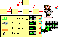
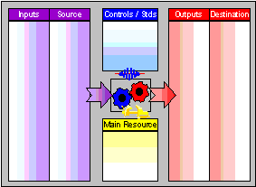
The logic of Process Redesign
is that if you can determine exactly what all the bits of the
process should be doing, and then refine them and develop them
to do this consistently well - the output of the process will
look after itself (see diagram to the right)
[Return
to Top of Page]
Process
Mapping
 Process
Mapping (otherwise known as Flowcharting) provides a well proven
method for undertaking process improvement. It is the primary
vehicle for moving from Current Physical (Step 1 - see
above) to Current Logical (Step 2). It is also a valuable
tool in viewing inconsistencies and redesigning the process (Step
3) and in communicating the changes (Step 4). Process
Mapping (otherwise known as Flowcharting) provides a well proven
method for undertaking process improvement. It is the primary
vehicle for moving from Current Physical (Step 1 - see
above) to Current Logical (Step 2). It is also a valuable
tool in viewing inconsistencies and redesigning the process (Step
3) and in communicating the changes (Step 4).
A Process Map is simply a graphical
way of representing the process flows and activities. Done properly
it can bring real understanding to a group and develop a clear
picture of what actually happens and any obvious issues or inconsistencies
within it. It also forms a catalyst for the team to talk about
process problems as they experience them in practice.
Process mapping uses a small
number of simple symbols to represent what happens in reality.
The description of physical events is written into the symbols.
The symbols should be used as they are defined here - in practice
many people only realise the importance of this discipline when
they get into problems with their first process map. The mapping
symbols are:
Formal Symbols
 A
yellow rectangle to represent an activity. Activities should
always be expressed using at least one verb (doing word) and
one noun (object word). A
yellow rectangle to represent an activity. Activities should
always be expressed using at least one verb (doing word) and
one noun (object word).
 An
arrow is used purely to link one symbol to the next. It indicates
precedence (order) only and should never be used to indicate
the flow of material or information (though this is a common
mistake) An
arrow is used purely to link one symbol to the next. It indicates
precedence (order) only and should never be used to indicate
the flow of material or information (though this is a common
mistake)
 A
blue diamond is used to represent a decision point where the
flow of the process may go different ways depending on the outcome
of the decision. The most common use of it is to write the decision
question in the symbol, and draw two arrows coming out of it
- one labelled 'yes' and the other 'no'. For more complex decisions
it is possible to put more than two arrows coming out, each with
the answer to which they relate written on them. A
blue diamond is used to represent a decision point where the
flow of the process may go different ways depending on the outcome
of the decision. The most common use of it is to write the decision
question in the symbol, and draw two arrows coming out of it
- one labelled 'yes' and the other 'no'. For more complex decisions
it is possible to put more than two arrows coming out, each with
the answer to which they relate written on them.
 Green
(start) or red (stop) round-ended boxes are used to mark the
start and finish(es) of the Process Map. Green
(start) or red (stop) round-ended boxes are used to mark the
start and finish(es) of the Process Map.
Informal Symbols
While these symbols are not part
of the formal system they can be useful in noting concerns, issues
and ideas which might otherwise be forgotten, sidetrack the discussion,
or cause members of the team to fret over remembering them and
disengage with what is happening in the meeting. We have found
them very useful in this regard.
 Grey
clouds can be used where the team is currently unaware of what
actually happens in the process. These are only a temporary symbol,
and should be replaced when the detail of the process is understood.
They are however useful in getting the mapping team past an impasse
without them having to make things up. Grey
clouds can be used where the team is currently unaware of what
actually happens in the process. These are only a temporary symbol,
and should be replaced when the detail of the process is understood.
They are however useful in getting the mapping team past an impasse
without them having to make things up.
 Red
flashes are useful to record concerns the team has about how
the process works in practice. These are most commonly used when
the process as drawn is sometimes not followed, and can be used
to note the issue. Red
flashes are useful to record concerns the team has about how
the process works in practice. These are most commonly used when
the process as drawn is sometimes not followed, and can be used
to note the issue.
 Green
ellipses are used to record the guidance that might be referred
to in making a decision or undertaking an activity. They are
useful for noting the control mechanisms that are in place without
having to over complicate the actual process map. Green
ellipses are used to record the guidance that might be referred
to in making a decision or undertaking an activity. They are
useful for noting the control mechanisms that are in place without
having to over complicate the actual process map.
 Blue
clouds are used to record ideas and suggestions as they occur
to people - in particular burning suggestions as to how things
could be improved or made different. They form a useful outlet,
and have many times prevented a discussion being totally derailed. Blue
clouds are used to record ideas and suggestions as they occur
to people - in particular burning suggestions as to how things
could be improved or made different. They form a useful outlet,
and have many times prevented a discussion being totally derailed.
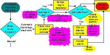
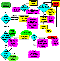 A
lot of software now exists for mapping processes on a computer
(eg Flowcharter, Visio) and this is a very good way of documenting
Process Maps, of re-designing them, and of keeping them updated.
The example diagram on the right was produced using Visio. A
lot of software now exists for mapping processes on a computer
(eg Flowcharter, Visio) and this is a very good way of documenting
Process Maps, of re-designing them, and of keeping them updated.
The example diagram on the right was produced using Visio.
We would however recommend that
flowcharts are always produced on flipcharts in the first instance,
and stuck around the room so the whole mapping team can see them
and remain engaged.
Though this approach is more
time consuming in changing and correcting mistakes, it is many
times better at getting to the truth of what happens and ensuring
the full attention of all assembled.
[Return
to Top of Page]
PDCA
 PDCA
stands for Plan, Do, Check, Act. PDCA
stands for Plan, Do, Check, Act.
This cycle of activity, also
known as the Deming Wheel, was developed by W. Edwards Deming
(the father of Total Quality) to represent how improvement should
take place:
Plan represents the need to think through
exactly what you are going to do before you do it.
Do represents the undertaking of the activity
that has been planned, and to ensure it happens as planned.
Check represents the need to review the results
and impact of the activity in an objective and analytical manner.
Act represents the need to make changes
to future plans in order to incorporate the learning from 'Check'.
 People
who are involved in training will note a number of similarities
with Kolb's learning cycle. The concept is a very simple one,
and some might think it is trivial or 'obvious', but it is quite
amazing how poorly it happens in practice. It is our experience
that most companies will have many examples of doing the first
two steps poorly, and even more examples of missing out the last
two steps completely. People
who are involved in training will note a number of similarities
with Kolb's learning cycle. The concept is a very simple one,
and some might think it is trivial or 'obvious', but it is quite
amazing how poorly it happens in practice. It is our experience
that most companies will have many examples of doing the first
two steps poorly, and even more examples of missing out the last
two steps completely.
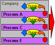
PDCA is embodied in the systematic
management approach (see the diagram on the right), and the colours
of the wheel shown above have been done to match the various
elements of the systematic model. But it is still a useful acronym
to remember for the less structured tasks and activities that
may fall outside of your formal systematic approach.
[Return
to Top of Page]
Simulation
 Process
Simulation is a technique where the activities and flows of a
process are represented mathematically, and the process is then
operated as a model, either on a computer or using something
resembling a giant gaming board, to ascertain how the process
is likely to work in practice given certain situations. Process
Simulation is a technique where the activities and flows of a
process are represented mathematically, and the process is then
operated as a model, either on a computer or using something
resembling a giant gaming board, to ascertain how the process
is likely to work in practice given certain situations.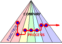
Process simulation can be very
valuable in looking at cycle times and the effect of backlogs
or batching on the flow of a process. Specialist process simulation
software is available, but much can be done using simple spreadsheets
or database packages such as Excel or Access.
Process simulation can do much
to illustrate the effect of different departments approaches
on the overall process. And the thinking involved in developing
the simulation is a good discipline for understanding exactly
what is important in the process in terms of cycle time, quality,
decision points etc.
[Return
to Top of Page]
Process
Analysis
 Process
analysis is the means by which existing processes can be objectively
analysed to evaluate how effective and efficient they actually
are. Exactly how the analysis is undertaken depends on the depth
of understanding that needs to be developed and the level of
documentation and data that already exists, but in general analysis
is likely to work through the following steps: Process
analysis is the means by which existing processes can be objectively
analysed to evaluate how effective and efficient they actually
are. Exactly how the analysis is undertaken depends on the depth
of understanding that needs to be developed and the level of
documentation and data that already exists, but in general analysis
is likely to work through the following steps:
1. A general investigation of
the quality of definition of the process, such as its objectives,
scope, content, and the extent to which that definition is understood
by those involved in the process.
2. A (theoretical) evaluation
of how the 'design' of the process, and the standards and practice
set within it meet the defined objectives. In many cases the
'design' will be more implicit (in existing custom & practice)
than explicit, but it will exist.
3. A more hands on evaluation
of the process through surveying the operators and customers
of the process to determine the main strengths and issues in
the process - this is likely to provide further insight into
1 & 2 above.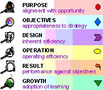
4. The collection of performance
data, and the quantification of key issues defined in 3 above.
The data is evaluated against the defined objectives, quality
standards and needs of the business.
5. An overall evaluation of the
current process based on the above, and an evaluation of how
well equipped the process is to adapt to such learning and to
future change.
Process Analysis is clearly only
valuable inasmuch as it leads to an improvement in all of the
above. The link between Process Analysis and the systematic model
can be seen in the diagram to the right.
[Return
to Top of Page]
Process
Metrics
 Process
metrics are the 'measurements' which monitor the extent to which
a process controllably and predictably fulfils its operating
and performance objectives. These measurements can be output
measurements or in-process measurements (which are often the
output measures of sub-processes), or in some cases input measurements. Process
metrics are the 'measurements' which monitor the extent to which
a process controllably and predictably fulfils its operating
and performance objectives. These measurements can be output
measurements or in-process measurements (which are often the
output measures of sub-processes), or in some cases input measurements.
In the simplest sense these measures
can be collected and averaged, and used to provide an analysis
of process performance and issues, which can then be worked on
to improve the process. (See section above on Process Analysis).
 A
more sophisticated use of process metrics is Statistical Process
Control (SPC) which can be used to trend these measurements,
and to predict quality issues and thus prevent them causing problems
'downstream'. SPC is used extensively in certain manufacturing
processes, but is not very much in evidence in clerical processes. A
more sophisticated use of process metrics is Statistical Process
Control (SPC) which can be used to trend these measurements,
and to predict quality issues and thus prevent them causing problems
'downstream'. SPC is used extensively in certain manufacturing
processes, but is not very much in evidence in clerical processes.
Process Metrics have a lot to
offer in ensuring high performance and quality, but are often
avoided for reasons of anticipated bureaucracy. Measurement does
take time and effort. However a 2% overhead in administration,
though it might seem wasteful at first glance, is more than justified
by a 10% improvement in performance.
[Return
to Top of Page]
Management
& Planning Toolkit
 One
of the real strengths of the Japanese is a tendency to standardise
and simplify wherever possible. One
of the real strengths of the Japanese is a tendency to standardise
and simplify wherever possible.
Faced with an ever increasing
number of management tools and approaches to the management process,
JUSE (the Japanese Institute of Scientists and Engineers) undertook
a long term project to evaluate which tools were bringing benefits
in practice, and to reduce these down into a standard set which
could be used anywhere.
This work concluded after a number
of years research in what is known as the Seven Management and
Planning Tools. Seven simple tools which address practically
all management and decision making situations, and which can
be learnt quickly and applied in teams. The result is both simple
and profound. Simple in terms of the mechanics - profound in
terms of the insights that can be developed from them.
Two of the tools are matrices
(one for looking at interactions, the other for prioritising)
which have been combined to form the QFD (Quality Function Deployment)
approach covered in the section on Philosophy. The other five
are:
The Affinity
Diagram
The Tree
Diagram
The Process Decision
Program Chart
The Activity
Network Diagram
The
Interrelationship Digraph
These tools offer a great deal
to the management process, and help to establish a formal process
in areas of decision making where process is often difficult
or sometimes non-existent. The remaining five tools are shown
below:
[Return
to Top of Page]
 The Affinity
Diagram is a tool for
looking at patterns and for grouping and summarising ideas. It
is also known as the silent sorting technique, and is most commonly
used at the end of a 'brainstorming' session where many disparate
thoughts have been collected. Each of the thoughts (ideas, issues,
activities, ...) are written on a separate sticky-note, and these
are stuck up randomly on a large flat wall (check this out beforehand
- not all wall surfaces work, and not all sticky-notes either).
The participants then move one note at a time, in total silence,
to place it with other similar notes, and this continues until
the pattern settles down, at which point the resulting 'affinities'
or groups of ideas are summarised (not categorised) and labelled. The Affinity
Diagram is a tool for
looking at patterns and for grouping and summarising ideas. It
is also known as the silent sorting technique, and is most commonly
used at the end of a 'brainstorming' session where many disparate
thoughts have been collected. Each of the thoughts (ideas, issues,
activities, ...) are written on a separate sticky-note, and these
are stuck up randomly on a large flat wall (check this out beforehand
- not all wall surfaces work, and not all sticky-notes either).
The participants then move one note at a time, in total silence,
to place it with other similar notes, and this continues until
the pattern settles down, at which point the resulting 'affinities'
or groups of ideas are summarised (not categorised) and labelled.
Silence is important - not being
able to explain your own point of view forces you to try and
resolve matters by trying to see what the other person is seeing.
In practice allow twenty minutes for an Affinity Diagram, or
two hours if you allow people to talk their way through it!
Return
to Management & Planning Toolkit Overview
 The Tree
Diagram is a tool to
explore exactly what needs to be done in order to achieve a goal.
The tree starts at the left with the goal to be achieved, and
then branches to the right into progressive levels of detail
as to how each objective and task breaks down into more detailed
objectives and tasks. The Tree
Diagram is a tool to
explore exactly what needs to be done in order to achieve a goal.
The tree starts at the left with the goal to be achieved, and
then branches to the right into progressive levels of detail
as to how each objective and task breaks down into more detailed
objectives and tasks.
The Why-How Chart outlined in
the section on Purpose is a form of the Tree Diagram, but it
tends to develop the trunk of the tree out of the branches (ie
to arrive at the top-level objective by thinking through more
detailed objectives).
The Tree Diagram should culminate
at the far right in a complete list of all the tasks that are
required to fulfil the main task or objective listed on the left.
Return
to Management & Planning Toolkit Overview
 The Process Decision
Program Chart (PDPC)
Is very similar in many ways to the Tree Diagram, but is specifically
intended to look at all the decisions and uncertainties that
exist in moving from the current situation to the intended future,
and to look at all the possible outcomes and the contingencies
for those that are unwanted. The Process Decision
Program Chart (PDPC)
Is very similar in many ways to the Tree Diagram, but is specifically
intended to look at all the decisions and uncertainties that
exist in moving from the current situation to the intended future,
and to look at all the possible outcomes and the contingencies
for those that are unwanted.
The PDPC can be used to extend
the tree diagram to look at what can go wrong in all the detailed
activities and to plan how such problems may be avoided or overcome.
This can be done for all areas or, more appropriately, can be
focused on areas that are particularly important or risky.
Return
to Management & Planning Toolkit Overview
 The Activity
Network Diagram is very
similar to P.E.R.T. approach commonly used in project planning
and management. The diagram starts on the left hand side, and
links the activities that need to take place to achieve the goal
(right hand side) in the order of precedence that they must occur.
Tasks that need other tasks to be completed before they can take
place, are placed to the right of them and linked by an arrow.
Activities that can take place in parallel are placed above and
below each other to show that they are in separate chains of
events. The Activity
Network Diagram is very
similar to P.E.R.T. approach commonly used in project planning
and management. The diagram starts on the left hand side, and
links the activities that need to take place to achieve the goal
(right hand side) in the order of precedence that they must occur.
Tasks that need other tasks to be completed before they can take
place, are placed to the right of them and linked by an arrow.
Activities that can take place in parallel are placed above and
below each other to show that they are in separate chains of
events.
The tool is key to developing
an efficient approach to delivering the goal in the shortest
possible time. It is commonly used for developing a time plan
of the activities arising out of the Tree Diagram, or out of
the PDPC.
Return
to Management & Planning Toolkit Overview
 The
Interrelationship Digraph
is often used to further explore the groups that develop out
of the affinity diagram. It is intended to enable people to see
links and causal relationships. The
Interrelationship Digraph
is often used to further explore the groups that develop out
of the affinity diagram. It is intended to enable people to see
links and causal relationships.
The Digraph is produced by placing
all of the factors (eg groups from an Affinity Diagram) onto
a large piece of paper in an initially random fashion. These
factors are then linked by arrows to represent causal effects
- eg the factor at the head of the arrow is 'caused' by the factor
at the tail.
The number of arrows converging
on, or emanating from, a factor can provide indications of root
causes, and other problems, and any loops in the arrows can indicate
vicious circles (or virtuous cycles).
Return
to Management & Planning Toolkit Overview
[Return
to Top of Page]
Home - Load
frames - About us - Resources
- Contact us
© Tesseract
Management Systems Ltd 2003
|

 Process

 QFD,
described in some detail in the
  QFD
drives the Management to consider the correct organisation of
its processes in concept, and then to translate this understanding
into an appropriate design. Without this the cost of misalignment
or inefficiency in the process can prove very expensive, either
in terms of correcting it physically or in terms of the consequences
in overhead costs or loss of business. The diagram (right) illustrates
this: issues that would take minutes to address in the concept
stage, take hours if they have to be addressed in design (in
terms of changing procedures and plans etc.), take weeks if they
make it through to implementation (in terms of modifying or re-ordering
plant etc.), and can cost many times that if left as a general
inefficiency or weakness in the business.
 The
concept of PROCESS is still not fully embedded in many companies.
A lot of companies still focus on departments and achievements,
rather than processes and performance. In part this is due to
their people not feeling fully confident in talking about business
processes - many have heard about Business Process Re-engineering
(BPR), and figure it is something you have 'done to you' unless
your lucky enough to avoid it until it fades away.
 There
is a model of learning which demonstrates how we pass through
4 stages in assimilating a new skill. The stages are: Unconsciously
Incompetent - we don't know that we don't know; Consciously Incompetent
- we discover our weakness in a particular area; Consciously
Competent - we get training or develop the necessary skills;
Unconsciously Competent - we become so adept that it happens
naturally almost without us realising that we are doing it. To
understand this better you might think it through for something
specific - eg driving a car.
 Step
4 (Future Physical) The changed map is implemented through changes
to procedures, re-training, machine re-design, new control systems
etc. as appropriate. The process then functions in the new way
until it comes time to review its performance and the cycle is
repeated (but with a lot less effort than the first time round!)
 Process
Mapping (otherwise known as Flowcharting) provides a well proven
method for undertaking process improvement. It is the primary
vehicle for moving from Current Physical (Step 1 -
  A
lot of software now exists for mapping processes on a computer
(eg Flowcharter, Visio) and this is a very good way of documenting
Process Maps, of re-designing them, and of keeping them updated.
The example diagram on the right was produced using Visio.
 PDCA
stands for Plan, Do, Check, Act.
 People
who are involved in training will note a number of similarities
with Kolb's learning cycle. The concept is a very simple one,
and some might think it is trivial or 'obvious', but it is quite
amazing how poorly it happens in practice. It is our experience
that most companies will have many examples of doing the first
two steps poorly, and even more examples of missing out the last
two steps completely.
 Process
Simulation is a technique where the activities and flows of a
process are represented mathematically, and the process is then
operated as a model, either on a computer or using something
resembling a giant gaming board, to ascertain how the process
is likely to work in practice given certain situations.
 Process
analysis is the means by which existing processes can be objectively
analysed to evaluate how effective and efficient they actually
are. Exactly how the analysis is undertaken depends on the depth
of understanding that needs to be developed and the level of
documentation and data that already exists, but in general analysis
is likely to work through the following steps:
 Process
metrics are the 'measurements' which monitor the extent to which
a process controllably and predictably fulfils its operating
and performance objectives. These measurements can be output
measurements or in-process measurements (which are often the
output measures of sub-processes), or in some cases input measurements.
 A
more sophisticated use of process metrics is Statistical Process
Control (SPC) which can be used to trend these measurements,
and to predict quality issues and thus prevent them causing problems
'downstream'. SPC is used extensively in certain manufacturing
processes, but is not very much in evidence in clerical processes.
 One
of the real strengths of the Japanese is a tendency to standardise
and simplify wherever possible.


